We used the PCB machine Cube3D MxPro. Here is a detailed explanation of the process and using the machine:
A strong and stable table is needed to place the machine. It is very heavy so the table needs to support its weight and it also needs to be stable to avoid vibrations which could mess with the accuracy of the process. The button to turn the machine on is on the back.

This PCB machine holds the PCB board in place by using a vacuum system that secures it onto an MDF surface. This keeps the board completely flat which is important for getting even cuts everywhere in the board during the cutting process. We connected the vacum to the back of the machine.
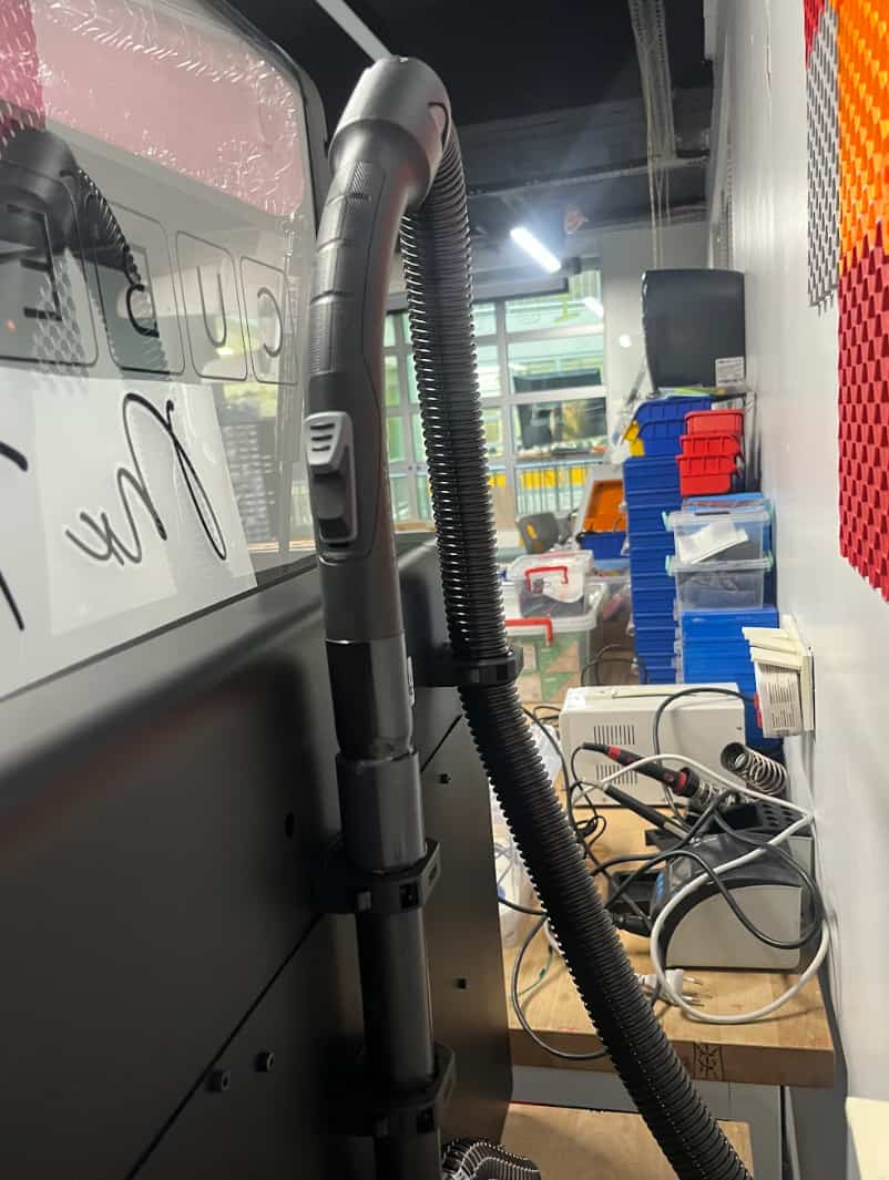
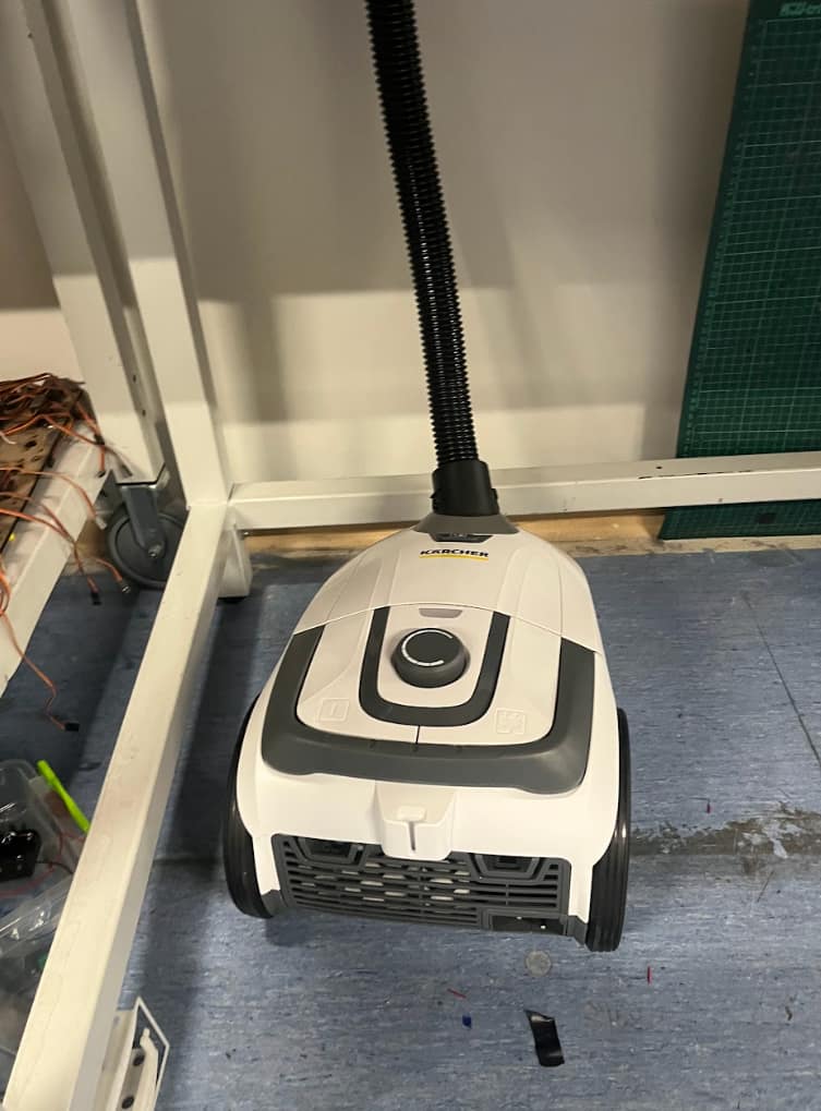
And placed it on the floor under the table. The button on the left turns it on. The vacum has to be turned on when working.
We have two software programs to work with the machine; Cube 3D Cam Pro and UCCNC.
Cube 3D Cam Pro:
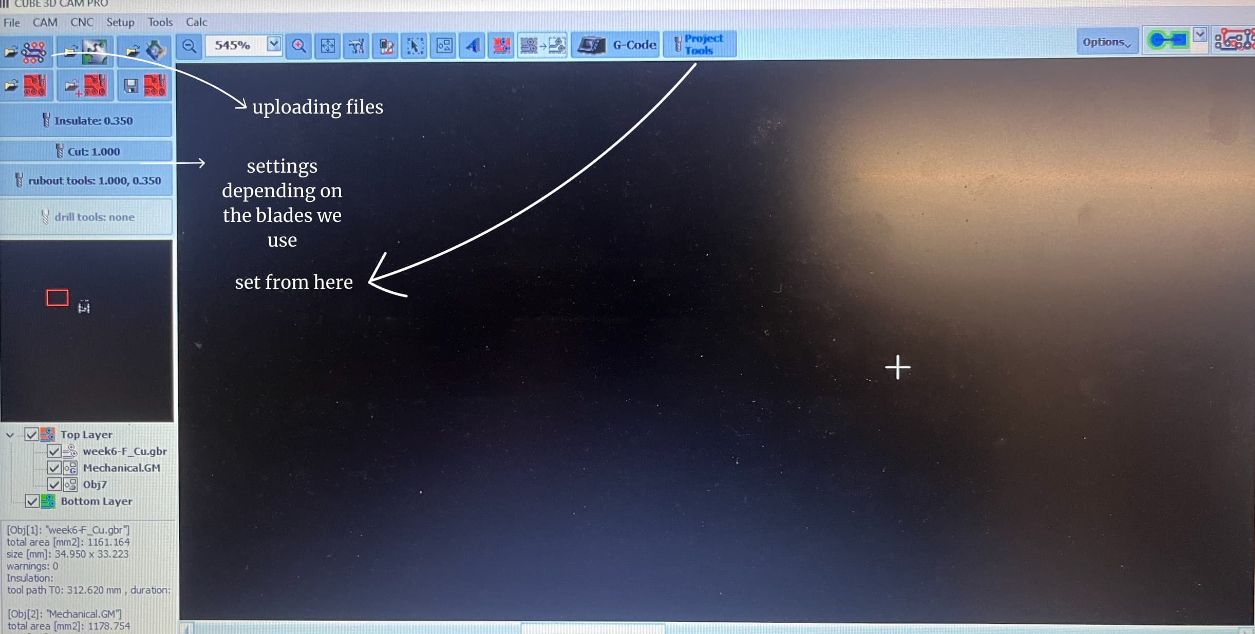
After clicking the uploading file button and opening our file we chose the appropriate Layers:
This has to be plugged in while generating g code.
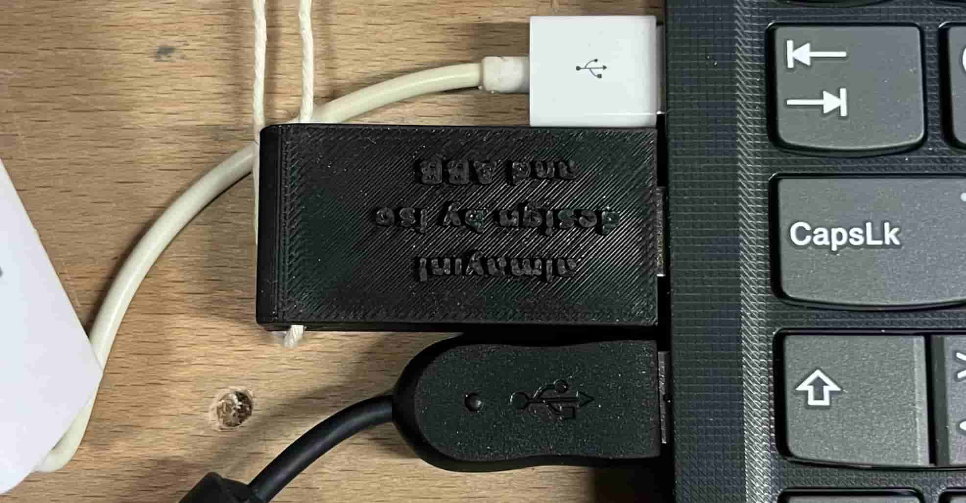
We made sure it was plugged in during the whole process and generated g code.
After that we switched to UCCNC
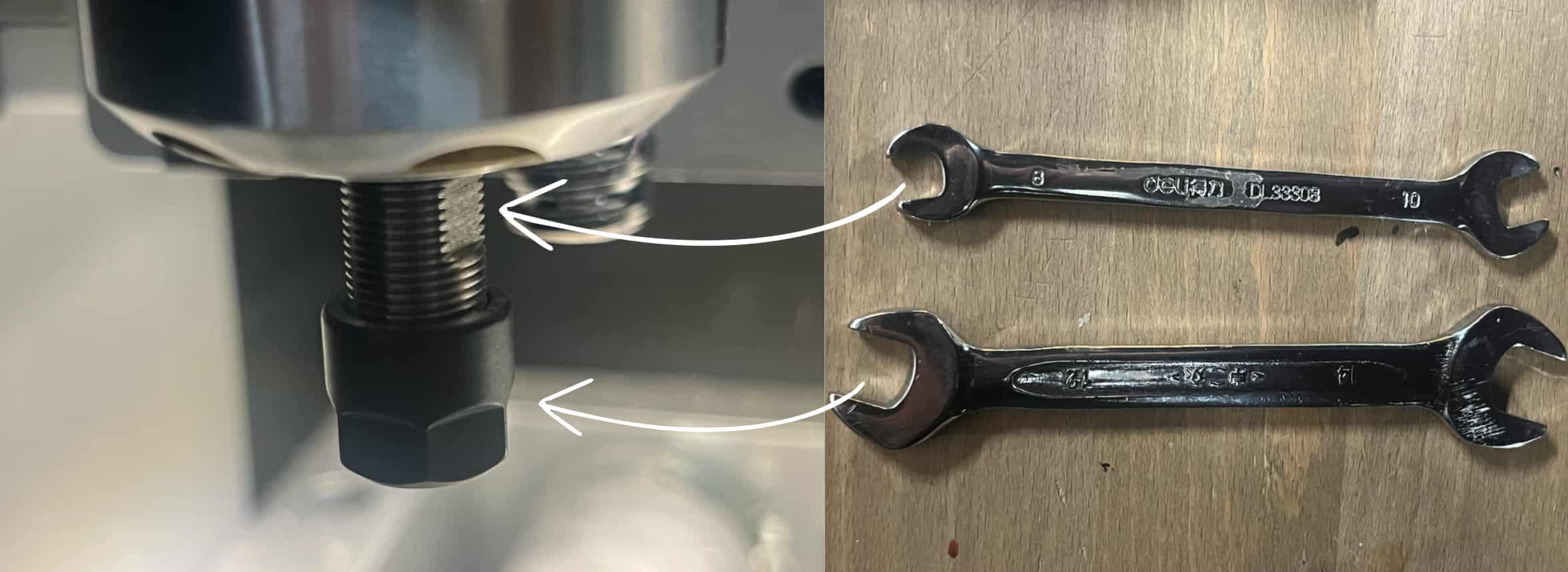
Here are the blades we used, the one on the right for engraving and the one on the left for cutting:

This is where we plug the blades in. We do it with the help of these tools and we make sure twist it good so it doesnt fall during the cutting process. 8 goes on the top and 12 goes on the bottom part.
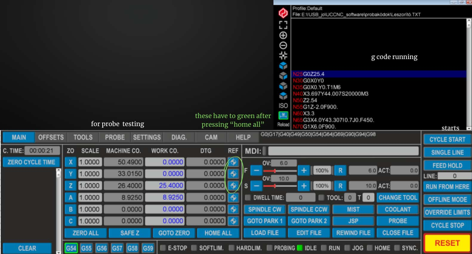
After we put in the engraving blade (first engraving, then cutting) we followed the following steps on the UCCNC software: home all > go to park 2 > zero all > probe test > cycle start.
home all > go to park 2 sets the zero coordinates for x and y so we also need to click zero all after going to park 2.
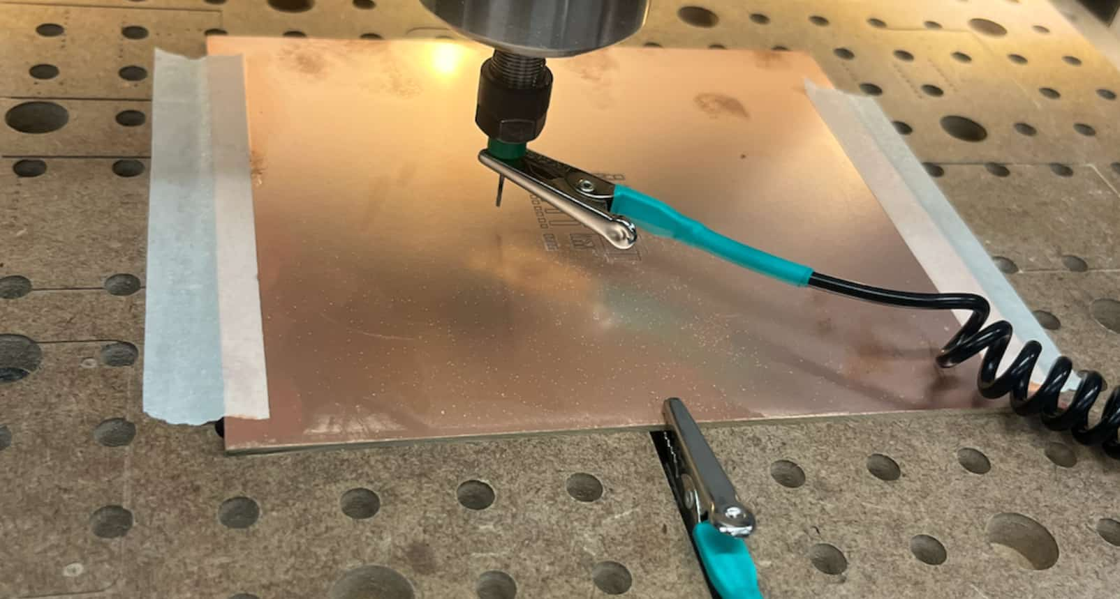
Probe test sets the coordinate to 0 for z direction so we dont click zero all after probing because probing basically sets the z coordinatesFor probing we went to the probing section and connected the two metal pins, one to the board and one on the blade. Pressing Fn+arrow moves the head around (pressing shift makes it faster). We moved the head as close as possible to the board without it actually touching it. During the probe test the head moves down to the board slowly and touches it twice.
Here are the files we used.
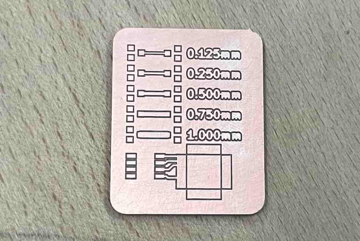
With printing out this design we tested the different trace widths labeled 0.125mm, 0.250mm, 0.500mm, 0750mm, 1.000mm
Here are the test results:
